LMATS has the capability to perform on site PMI using the latest Portable O.E.S. Optical Emission Spectroscopy inspection and testing methods.
(PMI by Portable Spark spectrometer)

Measure Carbon and Boron in In-situ Steel or Iron parts using Portable O.E.S

Portable Optical Emission Spectrometer (OES) also commonly known as portable spark PMI is battery operated handheld instrument that can be conveniently carried on site and perform chemical analysis of in-situ parts without damaging or reducing the usability of the component. LMATS has multiple units stored at various branch laboratories to meet client demand. Moreover analysis interpretation by LMATS full time employed Metallurgist, Materials engineers.

Despite its portability, it offers high analysis performance and accuracy of test results. Where portable XRF Spectrometer is incapable of determining crucial elements such as C, P, S, Sn, As and B in steel Or Al, Mg, Si in Aluminium alloys; the LMATS Portable Optical Emission Spectrometer (OES) using a special UVTouch probe can measure these elements accurately.
portable Optical Emission Spectrometer
Chemical analysis of the test part can be completed within 5minutes (Average of 3 sparks) after adequate surface preparation. Required surface preparation is essentially bare metal polished to 120grit grinding paper. Analysis spark is protected from atmospheric contamination by using ultra high purity Argon gas.
For general sorting of metals, argon gas is not essential.

Ideal Applications:

  • Chemical composition of in-situ steel structures on bridges and plantsportable optical Emission Spectrometer2
  • Rapid positive material identification for large number of parts or components used in big pressure vessels and piping in the Petroleum, Chemical and Oil & Gas industry
  • Inspection of reinforcing bars, steel slabs and structural parts at the shipping dock
  • Requirement for Carbon equivalent of in-service pipeline prior to hot tapping
  • Chemical composition of in-situ Aluminium alloys
  • Requirements for reverse engineering of in-situ parts
  • Correct analysis of small diameter pipes by use of adaptor.

Following elements (including range) can be measured in steel parts.

ELEMENT Carbon Silicon Manganese Phosphorous Sulphur Chromium Molybdeum Nickel
% Min 0.0005  0.001   0.001   0.0005  0.0005  0.001   0.001   0.001 
% Max 4.75  20   0.8 0.4  35   11  52
ELEMENT Aluminium Cobolt Copper Niobium Titanium Vanadium Tungsten Zirconium
% Min 0.0005  0.0005  0.0003  0.0005  0.0005  0.0005  0.005  0.0005 
% Max 52  12 9 3.3 2.3 11 22 0.5
ELEMENT Arsenic Tin Boron Calcium Lead Magnesium Bismouth Zinc
% Min 0.0005  0.0005    0.0005  0.0005   0.0005   0.0005   0.0005   0.0005  
% Max  0.11 0.3 0.12 0.008 0.4 0.1 0.15 0.05
ELEMENT Nitrogen Tellurium Antimony Cerium Lanthanium Selenium Tantalum  
% Min 0.0025  0.0005 0.001 0.0004 0.0005 0.0005 0.005  
% Max 1.2  0.035 0.3 0.075 0.025 0.35 0.045  


Advantages:

  • Portable Optical Emission Spectroscopy OES has following advantages over conventional portable XRF
  • Carbon & Boron content can be determined in steel and iron parts
  • Stainless steel can be classified for 316L or 304L, etc
  • Nitrogen content can be measured in Duplex Stainless steel
  • Light elements Al, Mg, Si, etc can be accurately measured in Aluminium alloys
  • Portable Optical Emission Spectroscopy OES has following advantages over conventional sample collection by grinding/shaving, etc.
  • No need to damage in-service big castings, forgings, bridges, structures, pipelines, etc by cutting or extracting samples
  • No need to spend hours for sample collection by surface deburring, grinding or shaving on in-situ structures
  • Only 10x10mm area needs to be prepared as compared to a need larger area for shaving or grinding
  • Sample surface re-coating time reduced by 99%
  • Risk of rework (retest) due to sample contamination while shaving or grinding is eliminated
  • Portable Optical Emission Spectroscopy OES can be performed on hot or cold surface thus eliminating asset downtime.

Limitations:

  • Portable Optical Emission Spectroscopy (OES) is a spark spectroscopy. Hence it will require hot work permit
  • Portable Optical Emission Spectroscopy (OES) leaves a thermal burn spot on the test surface. This may not be acceptable on some components
  • Portable Optical Emission Spectroscopy (OES) consumes very high purity Argon gas. Hence site permit may be required to carry portable gas bottle on site.

Portable Optical Emission Spectroscopy (OES) FAQ's

Expertise:
Compared to XRF Spectroscopy, Portable Optical Emission Spectroscope (OES) requires extensive training and experience to obtain correct test results. This test method requires highly trained, skilled and experienced materials engineering professionals. LMATS staff are trained and experienced engineers to provide on-site chemical composition of your components.

LMATS offers Portable Optical Emission Spectroscopy (OES) regularly to its clients in VIC - Victoria (Melbourne, Ballarat, Bendigo, Dandenong, Wodonga, Gippsland), NSW - New South Wales (Albury, Wodonga, Sydney, Cooma, Newcastle, Coffs Harbour, Central coast), Qld – Queensland (Brisbane, Gladstone, Chinchilla, Rockhampton, Tasmania) WA – Western Australia (Perth, Bunbary, Collie, Pilbara, Karratha, Esperance, Geraldton, Mandurah, Kalgoorlie, Kambalda, Newman, Olslow), NT - Northern Territory and other states as required by our customers.

To find out more about LMATS Portable Optical Emission Spectroscope (OES) Capabilities simply contact one of the nearest LMATS branch or contact us on +61 3 9399 9199 to get instant information.

LFET – Low Frequency Electromagnetic Technique

Dry non-couplant testing on boiler tubes and small pipes

LFET is one of the electromagnetic test methods utilized effectively for the inspection and assessment of boiler wall tubes and any other small diameter ferrous or non-ferrous pipes. LFET can detect and quantify discontinuities on the OD surface, ID surface and within the wall thickness of the pipe.

LFET is a non-intrusive internal wall corrosion-erosion assessment method. As the name suggests, LFET utilizes low frequency electromagnetic energy to test Boiler Wall tubes and pipes. LFET instrumentation used for Boiler Wall tubes testing comprises a special purpose contoured probe (to match tube circumference) manual scanner, test equipment and a custom software for live detection of flaws.
 

A low frequency electromagnetic field is induced into the test material using an external horseshoe shaped electromagnet. Any flaw in the path of the magnetic field distorts the magnetic flux which is detected by the array of sensors. The severity of a discontinuity is measured by analyzing a Phase / Amplitude plane graph with the aid of a custom purpose software. 


 Rapid scanning of HVAC pipe at a data centre

Ideal Applications:

  • Boiler, superheater, heater & economiser water wall tubes
  • Ligaments, bends, space constricted areas between pipes.
  • Fire hydrant, air conditioning and refrigeration piping in commercial buildings
  • Air and other fluid piping in industrial plants
  • Extrados of tube bends in heat exchangers, side of tube bends, intrados of tube bends
  • Detection of 
    • Internal erosion, corrosion, localised pitting, wormholes, etc
    • Localised pitting in rifled boiler tubes
    • Caustic & phosphate gouging, Hydrogen damage or corrosion
    • Internal crack, SSC on SS, corrosion fatigue cracks on tubes near or at ligament interface

 LFET ligament scanner Ligament scan

Features:

  • Dry non-couplant test method
  • Traceable and accurate test outcome as compared to RT, ET, UTT
  • Real time, 3D full coloured mapping of defects for  visualisation of defects.
  • Rotating view, plan view and zooming for envisioning obscured defects.
  • Scanning through protective coating or uniform surface rust or scale is possible  
  • Scanning of 100% of the boiler wall tube surface in 2 or 3 scans for up to 100mm diameter pipes
  • Circumferential as well as axial cracks can be detected and quantified using EDM calibration pipe.


Advantages:

  • Uniquely separates pitting indication from a gradual wall loss.
  • Effective internal corrosion assessment method as compared to Visual and UT
  • Detect discontinuities on both the OD and the ID side of the boiler wall tube in the same scan
  • Faster scanning method as compared to PAUT, UTT, MFL, ET or RT. Scan speed = 3m/min with a 1200 pipe diameter coverage
  • Detect discontinuities while scanning of boiler tubes.
  • Cost-effective and economical as compared to CRT, UTT, PAUT, ET, PEC
  • Light weight scanner that can be attached to the SteerRover for scanning at heights without rope access or scaffolding or EWP.

Limitations:

  • Discontinuities detected by LFET requires further assessment using PAUT or UTT for measuring deepest defect.
  • Maximum 19mm wall thickness scanning.
  • Sensitivity is restricted to detect pit of approx. ø3mm at 30% depth. 
  • Requires >4 scan passes for pipe diameter greater than 100mm.
  • Maximum 13m cable length for remote inspection

Expertise:

Compared to conventional ET or UT, Low Frequency Electromagnetic Technique (LFET) test instrument and sensors are complex and expensive. This test method requires highly trained, skilled and experienced technicians.  LMATS provides certified and experienced engineers to complete LFET assessment to the clients.  LMATS offers LFET from our Melbourne, Sydney, Albury, Newcastle, Brisbane and Perth laboratories. LMATS regularly performs LFET in other regions of VIC -Victoria, NSW - New South Wales, QLD - Queesnland, QLD - Brisbane, SA - South Australia, TAS - Tasmania, NT -Northern Territory, WA - Western Australia and some of the countries aroung the world on request. Contact one of the LMATS branches near your location to obtain assistance for your next project.  You may contact us +61 3 9399 8145 or via the form

GW LRUT – Guided Wave Long Range Ultrasonic testing


Long Range Ultrasonic testing (LRUT) also known as Guided Wave Ultrasonic testing (GWUT) is an Ultrasonic method wherein ultrasonic waves are transmitted along the pipe wall (guiding walls) up to 180meters in length.


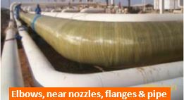
GW LRUT – Guided Wave Long Range Ultrasonic testing is a rapid screening test method for integrity assessment of pipelines, non-piggable buried, encased piping, vertical or inaccessible piping (e.g. overhead pipe racks) or epoxy coated pipelines to locate areas of potential degradation or engineering concerns and gross discontinuities for targeted assessment and inspection. While conventional NDT test methods provide localized inspection, underneath or in the vicinity of the sensors, LRUT is able to test 100% circumferential wall over tens of meters of the pipe length from the single inspection (contact point) location.


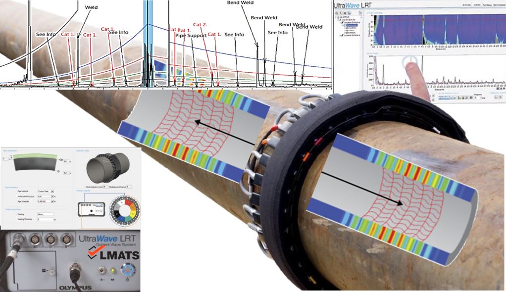
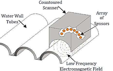
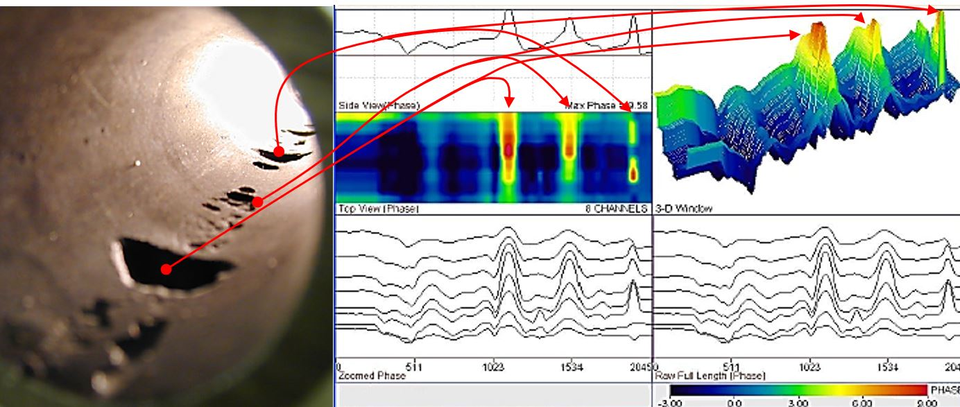
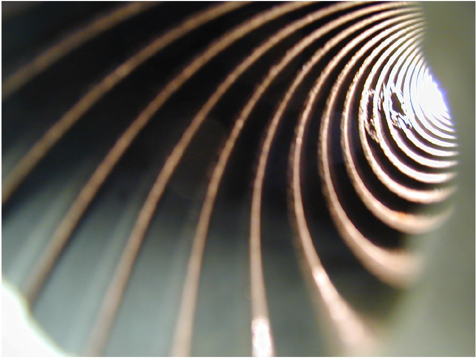
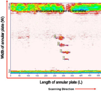
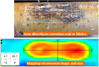
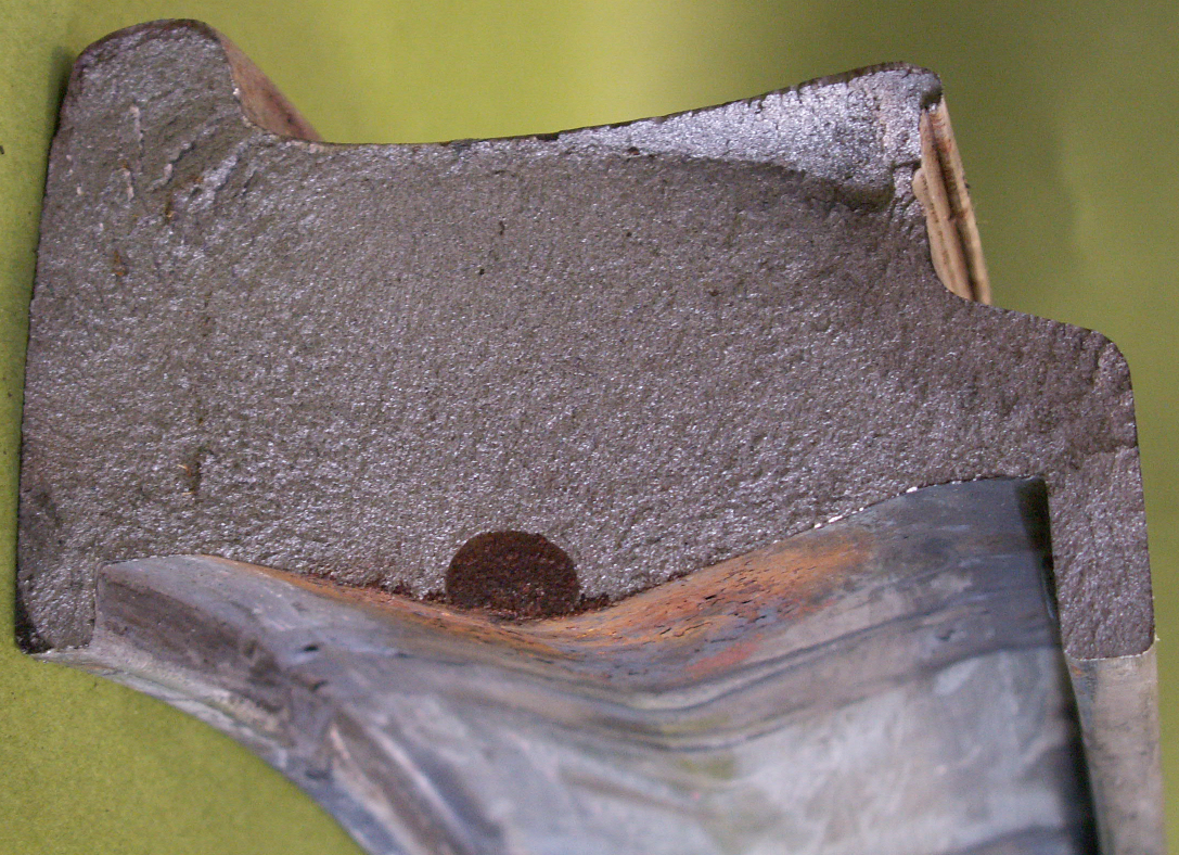
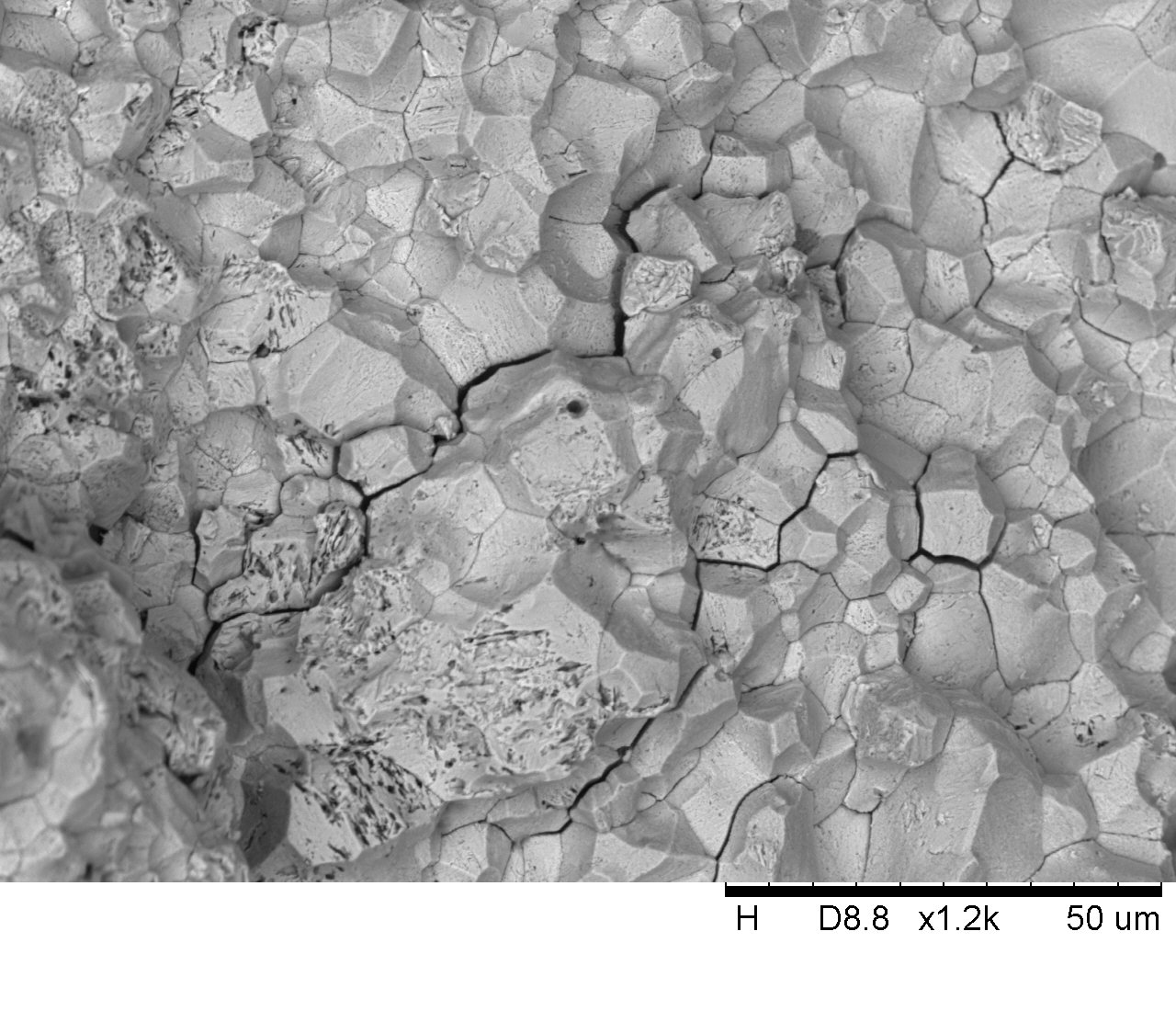
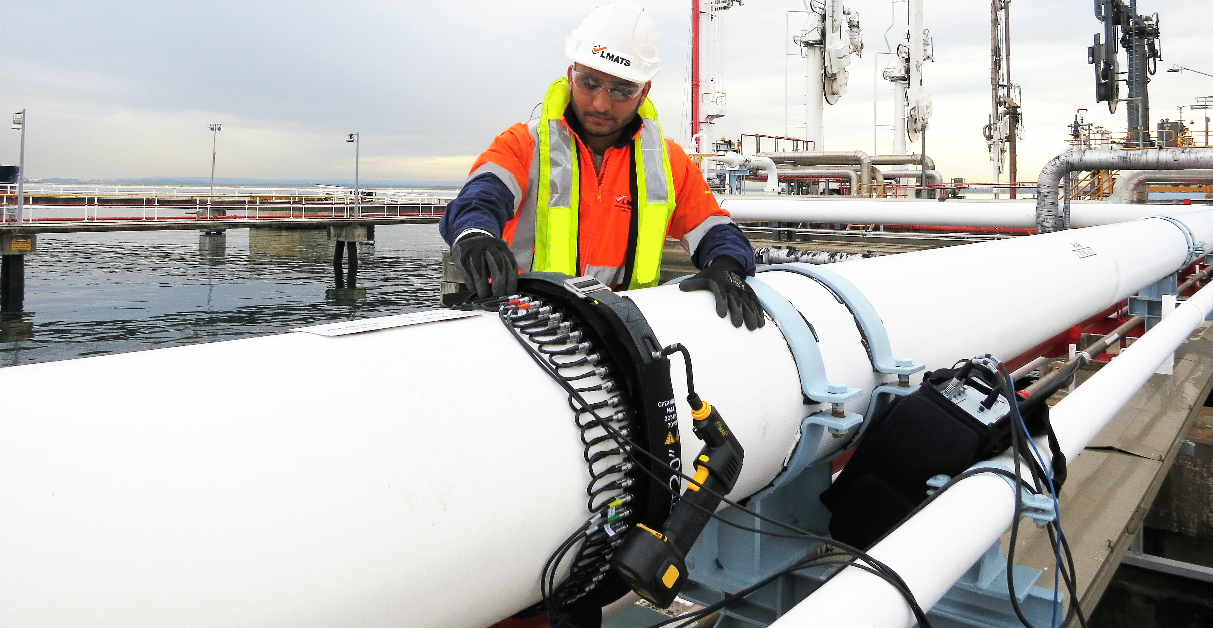
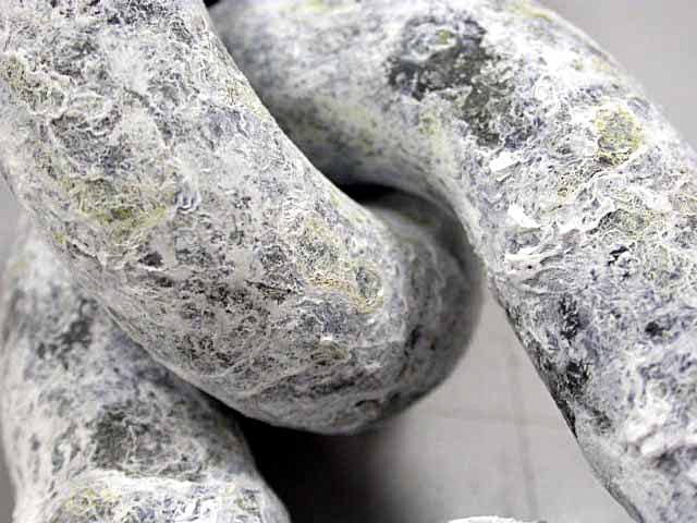
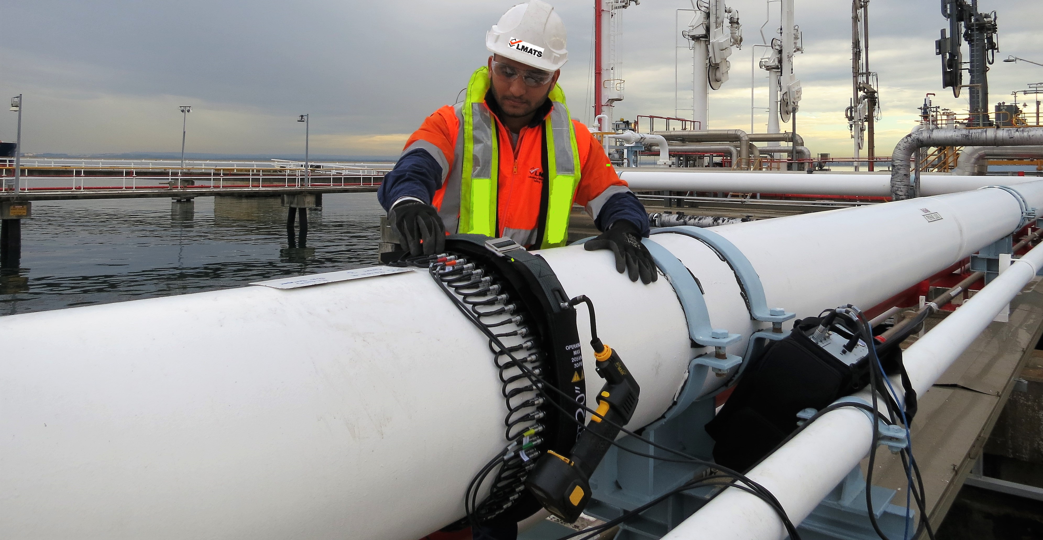
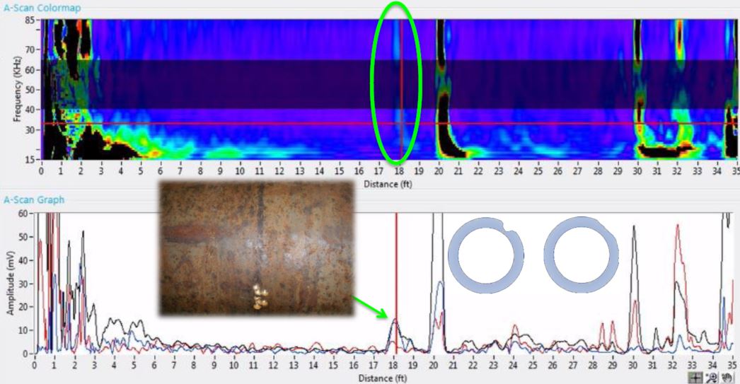
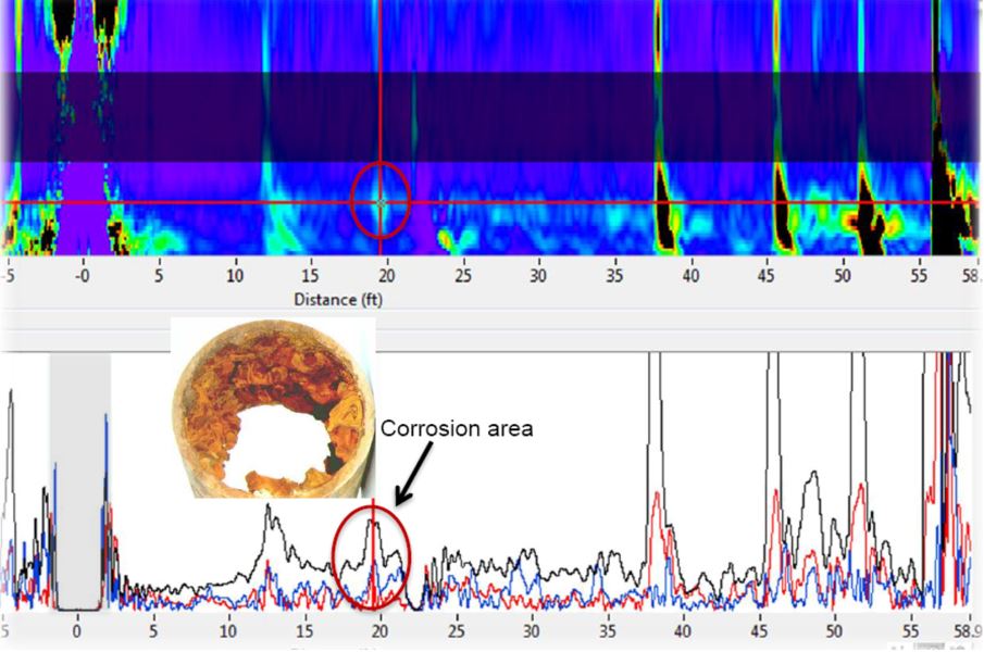
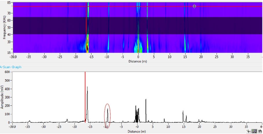
Guided Wave LRUT is used to inspect 100% of pipe circumference along the pipe length from a single location. Low frequency (15-85kHz) torsional or longitudinal guided waves are generated into the pipe body (360 degrees all around the pipe circumference) on both sides of the transducer assembly collar. These ultrasonic waves propagate in the axial direction of the pipe until the entire energy is attenuated or dissipated. When these guided waves intercepts areas of change in cross section such as butt welds, pipe supports, elbows, flanges or gross discontinuities such as severe corrosion, erosion, pitting clusters, etc; they reflect laminar waves back to the sensors at the location of wave initiation (Transducer assembly  Collar). Multiple frequency signals are acquired simultaneously and analysed. The time-of-flight for each reflection and its dominant frequency is analysed to determine its location from the sensor. The quadrants determine the feature’s circumferential position on the pipe wall. The amplitude of the signal determines the significance of the defect in relative loss of cross section (LCS). The minimum LCS (loss of cross sectional area) that can be currently confidently detected is 3% of the total cross sectional area of the pipe under examination. One of the examples of representative cluster is shown in the following image. 

Guided Wave LRUT is primarily applied on pipelines having limited access or only localised access; to avoid unnecessary excavation, coating removal or scaffolding installation. The use of LRUT significantly reduces maintenance costs and is a perfect inspection method for unpiggable pipes or inaccessible pipe sections. LRUT can be used on pipe diameters ranging from 38mm (1.5”) to 1200mm (48”) to detect loss of cross section (LSC) or areas of concern such as corrosion or erosion pockets around the pipe's circumference.  The sensitivity of the LRUT is typically 2.5% LSC, equally sensitive on both ID and OD of the pipe. Absolute defect size will depend on the pipe size (for large ODs and wall thickness, 5% can be a penetrating defect). The signal amplitude will depend on the shape of a discontinuity e.g. extended area over the circumference or the extended depth in the wall. LRUT can be performed on in-service pipelines operating in the range of 0°C to 70°C.  Testing can be done at higher temperatures and as low as -30°C but with exceptional risk management plans. Moreover, LRUT can be applied on various materials and different pipe diameters having wall thickness up to 40mm. 

ASTM E2775 outlines a procedure for using GWUT on tubular carbon steel or low-alloy steel products having Nominal Pipe size (NPS) 2" to 48", and for wall thickness between 3.8 and 25.4 mm.  


Typical scanning (interpretable) range from the single test location is the maximum ± 90 meters in each direction (180meters bidirectionally) for above ground or encased pipelines. The interpretation distance from the single location can be reduced by the following parameters.

  • Pipeline layout such as several bends, attachments, supports, branches & joints
  • Highly viscous liquid deposits on the internal or external pipewall.
  • Entire pipeline is severely corroded (Rapid attenuation of ultrasound and excessive noise reduces interpretable lengths of pipeline)
  • The type of coating e.g. Bitumin is a viscous liquid which dampens ultrasound.
  • Excessive thickness, diameter and the material of the pipeline

Generally, inspection range is set in relation to the defect size sought (sensitivity) and the attenuation of sound.

Ideal Applications:

Guided Wave Long Range Ultrasonic testing (GW LRUT) can be used for

  • Rapid inspection of in-service pipelines and piping for detecting corrosion or areas of concern (LCS)
  • Buried pipelines at the excavation locations or at level crossings
  • Encased (through-wall) pipelines or culvert line or PE coated pipes
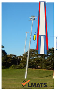
  • Vertical pipes or structural circular columns
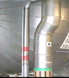
  • Inaccessible piping e.g. overhead piping rack
  • Requirement for high speed assessment to reduce cost reduction - Eliminate the cost of complete scaffolding or use of Elevated working platforms due to which testing speed is reduced.
  • Insulated pipelines and piping – No need to remove entire pipeline insulation
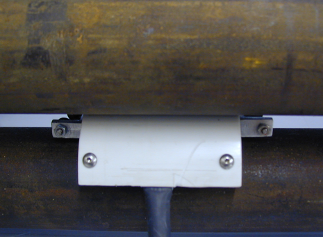
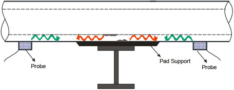
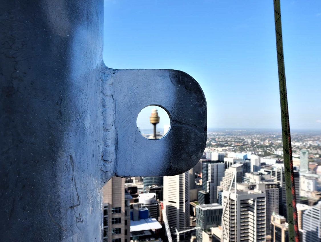
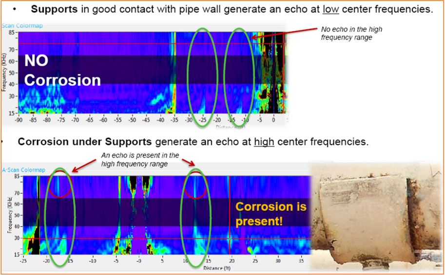
  • Detection of corrosion at pipe supports, clamps and pipe racks
  • Refinery, chemical plants, power station piping
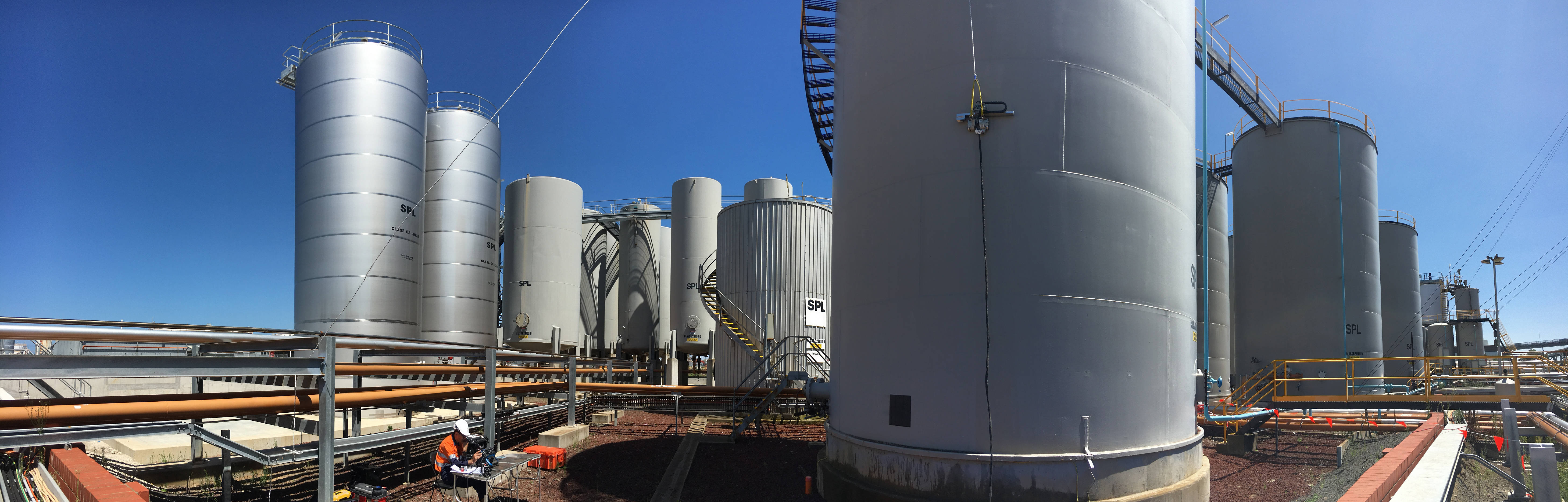
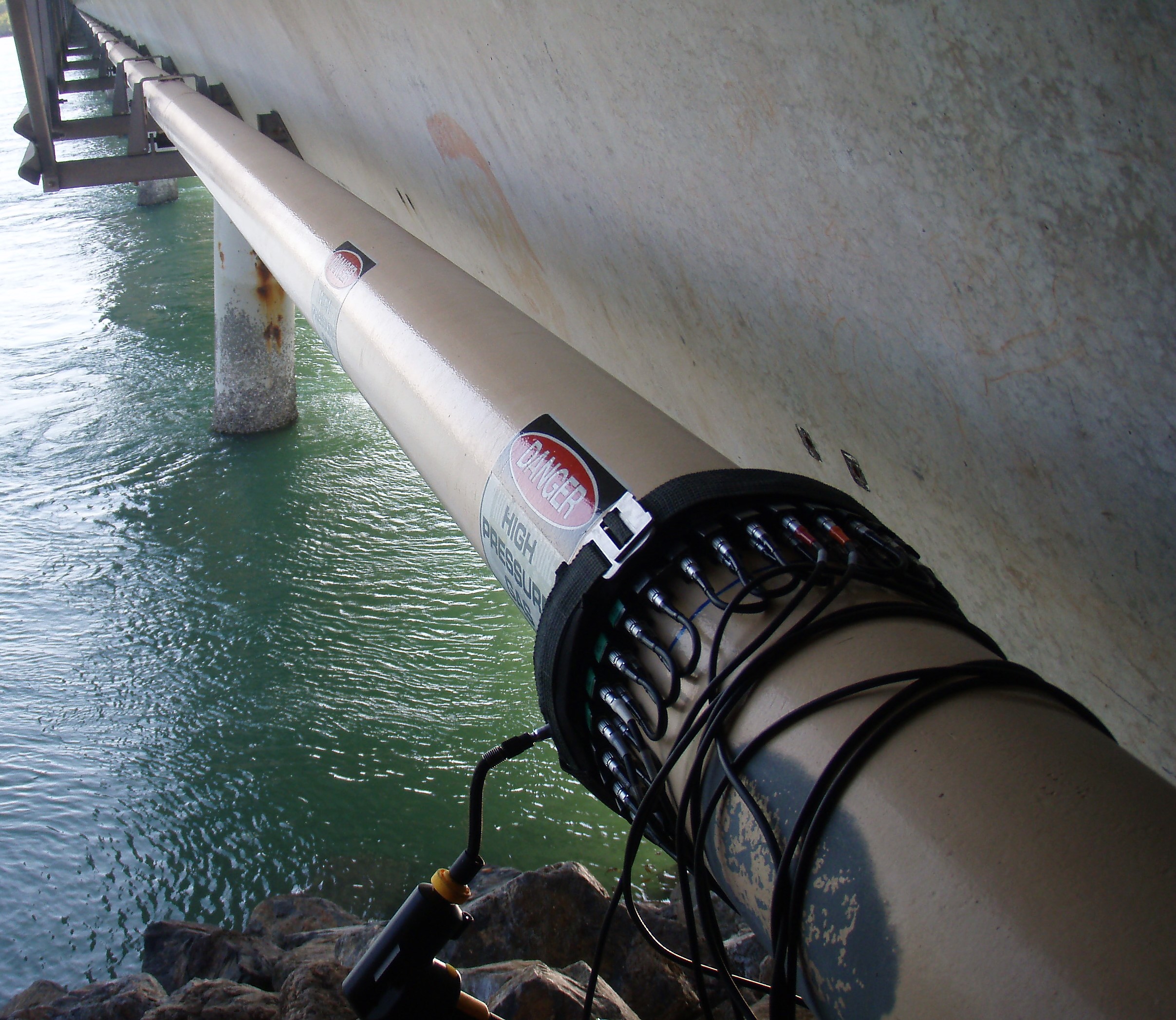
  • Risers and offshore topside pipe work
  • Jetty lines and river crossing pipelines, tank farm link lines and sewer lines
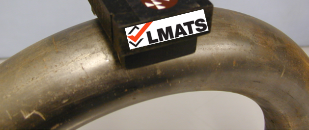
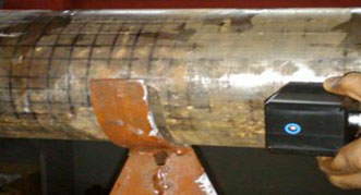
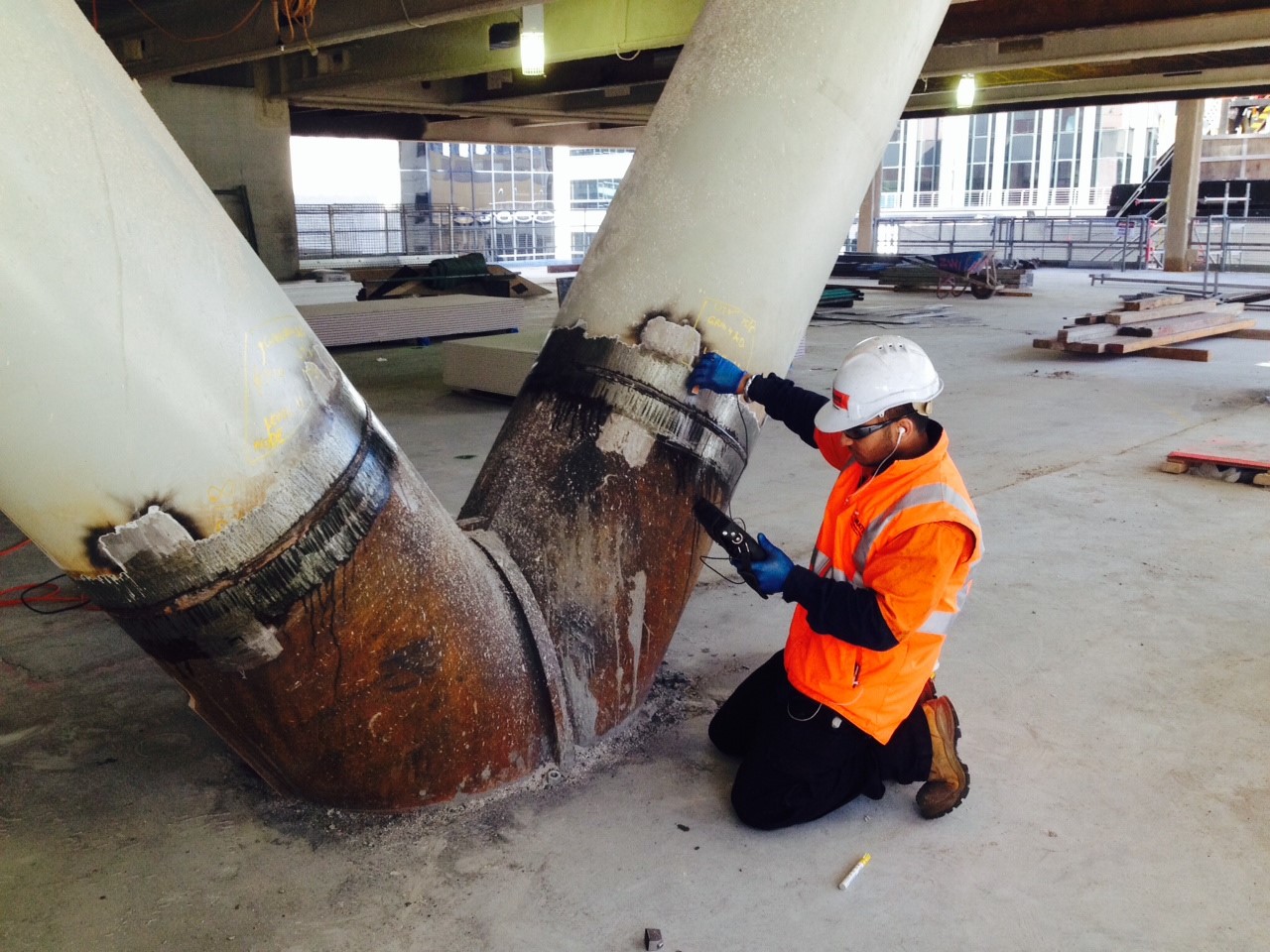
  • Detection of Weld Root Erosion (See following image)

Advantages:

  • In-service inspection prevents production losses or downtime.
  • High productivity inspection - Reduction in onsite inspection time – maximum examination speed is 180meters per hour.
  • Examine 180meters (90m from each side of the transducers) from the single test location
  • Examine 100% of the pipe circumferential wall from the single test location (contact point)
  • Maintenance cost reduction by not removing
    • surface coating of the entire pipeline except 500mm width exposed to attach transducers.
    • insulation of the entire pipeline, except 500mm exposed to attach transducers.
  • No need to sand blast or grind entire pipeline surface under examination
  • No need to excavate the entire non-piggable pipeline or random spot tests
  • No need for a couplant which is necessary in conventional ultrasonics.
  • Detects weld root erosion faster than conventional test methods
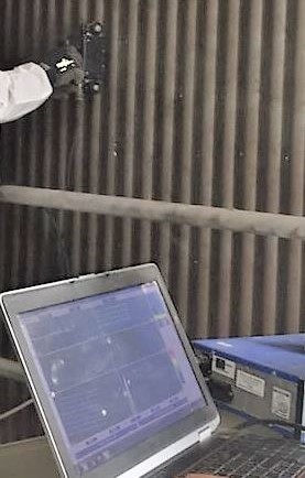
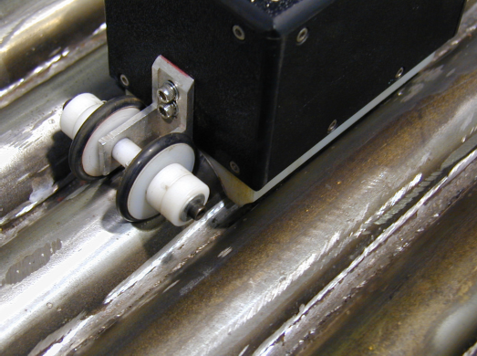
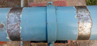
  • Detects corrosion (loss of cross section) at pipe support. See image below

  • Limitations:

    • Guided Wave LRUT is a screening test method and hence precise measurement of minimum wall thickness (like PAUT) is not possible. After an area of concern is detected, average wall thickness measurements can be completed by Pulsed Eddy Current testing (PECT) as a faster technology. For precise wall thickness measurements, Phased Array Ultrasonic testing (PAUT) is recommended. For localised wall thickness measurement, conventional compression (longitudinal) wave ultrasonic testing can be applied.
    • Cannot detect an Isolated pit.
    • Testing of Cryogenic pipelines is possible but difficult – Exposed test location will condensate heavily and also the transducer may not detach from the frozen pipe wall surface.
    • Bitumin coated pipelines or buried pipes in contact with wet soil and wet silt or severely pitted pipelines attenuate sound severely and hence they are difficult to inspect.
    • 100% surface area around the fillet weld cannot be assessed due to joint configurations.
    • Pipes less than 1.5inch diameter are currently not feasible to examine.
    • Minimum pipe length shall be 5meters for cost effective LRUT application.


Typical test range possible on different pipelines:

Pipeline type / condition Probable Test range (in each direction) Typical 
Minimum length Maximum length Attenuation
Clean straight pipe 50 200 -0.15 to -0.5dB/m
Kevlar wrapped 30 200 -0.15 to -1dB/m
Clean, wool insulated  40 175 -0.5 to -1.5dB/m
Insignificant minor corrosion 20 50 -0.5 to -1.5dB/m
Spun epoxy coating 30 50 -0.75 to -1dB/m
Significant corrosion 15 30 -1 to -2dB/m
Well packed earth 15 30 -1 to -2dB/m
Grout lined pipe 10 30 -1 to -3dB/m
Bitumen tape - thin (<2.5mm) hard 5 25 -1.25 to -6dB/m
Bitumen tape - thick (>2.5mm) soft 2 8 -4 to -16dB/m
Concrete wall - loosely  bonded 2 8 -4 to -16dB/m
Concrete wall - well bonded 1 2 -16 to -32dB/m

Steel Pylons / Piles or pipeline under water = Approximately 15m minimum 

Buried pipeline - dense clay embedded, Coal tar enamel coated in Victoria = 10m on each side of the Transducers


Expertise:

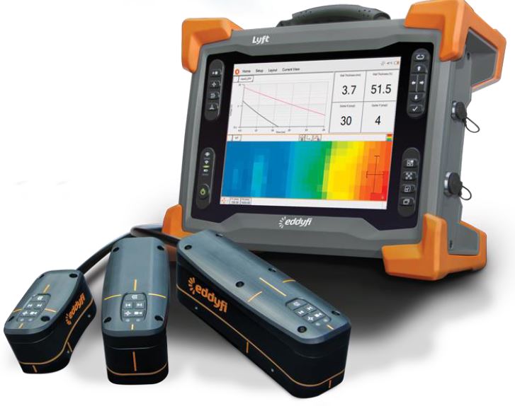
LMATS utilizes the latest technology LRUT instrument from Olympus, the UltraWave system. The UltraWave LRUT system is a higher resolution instrument as compared to some other technologies. One of the feature is having 1 kHz adjustable steps within a frequency spectrum of 15 to 85 kHz to evaluate signals better.  As the GWUT is frequency dependent analysis, the software for this latest technology LRUT system is equipped with a unique F-scan color map that displays the entire frequency range acquired over the inspected pipe length.  Olympus LRUT system also includes the active focusing capability to reduce signal-to-noise ratio which enhances flaw evaluation by delivering concentrated energy at a specific location on the pipe. The energy can be focused at eight different positions around the circumference, investigating the pipe cross-section, segment by segment. This active focusing estimates the circumferential extent of the indication by displaying a Polar graph.

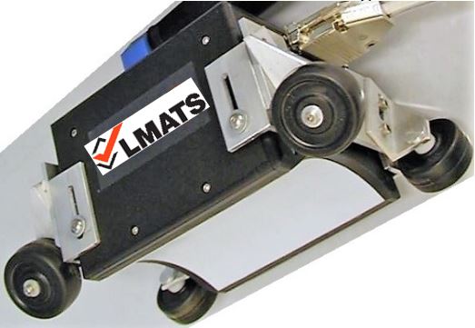
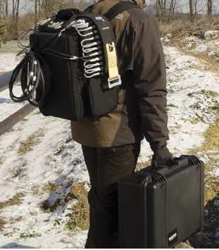
LMATS LRUT system is a portable back-pack carry on system (8kg), battery operated which can performed by a single person.


Compared to conventional ultrasonic testing, Guided Wave LRUT instrument, transducers and software are complex and thus expensive. This test method requires highly trained, skilled and experienced personnel.   LMATS  has trained, certified and experienced engineers to provide Guided Wave Long Range Ultrasonic testing (GW LRUT). 


LMATS offers Guided Wave Long Range Ultrasonic testing (GW LRUT) testing from our Melbourne, Sydney, Brisbane, Perth and Albury laboratories.  LMATS regularly performs Guided Wave Long Range Ultrasonic testing (GW LRUT) testing in VIC -Victoria, NSW - New South Wales, QLD - Queensland, WA - Western Australian, SA - South Australia, TAS - Tasmania, NT -Northern Territory and some of the neighbouring countries at request.

To find out more about LMATS Guided Wave Long Range Ultrasonic testing (GW LRUT) Advanced NDT Capability, simply contact one of our laboratories nearest to your location or call on + 9399 8145 or via the form


Frequently asked Questions:
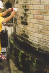
FAQ1What is the level of surface preparation required at the LRUT contact point?

Advice – If the coating system is of good quality and adequately adhered to the pipe surface then no additional need for surface preparation. But in most cases, the coating condition is of unacceptable quality or coating flaking off. Hence it is recommended to sand blast or remove surface coating of 500mm width around the pipe circumference. This location should be preferentially chosen away from a butt weld or a flange end.

FAQ2Can LMATS perform LRUT on my cast iron pipeline?

Advice – Yes, LMATS can perform LRUT on your cast iron pipeline, conditional to that the pipes are metallurgically bonded (e.g welded) and not joined by flanges or screw joints. If later is the case, then each pipe will need to be scanned individually using LRUT single point of contact system.

Graphitization is the common mode of corrosion in cast iron pipes. LRUT should be able to detect considerable graphitization (non-conductive layer) when the sound conductive loss of cross section has occurred. The sensitivity may not be as effective as it will be on carbon steel pipes.

Note – Most of the cast iron pipes are either bell type joint (with rubber inserts) making them conductivity wise non-continuous pipeline. Hence each of the pipes will require LRUT assessment. LRUT has a near zone effect of 1m. This means a typical 2.4m pipe will need scanning from both ends of the pipe.

Alternative for this is to use Magnetostrictive collars which produces slightly higher frequencies and has shorter near filed zone. This test method is like Short range guided wave ultrasonic.

If LRUT or SRUT is not a possibility for your pipe then MFL is recommended.


LRUT does not require couplant as is the case in conventional ultrasonic. But in-service cast iron pipe may have textured surface which may not permit LRUT dry coupling. 

FAQ3What types of materials can be inspected by LRUT?

Advice – Carbon steel, alloy steel, stainless steel, Cast iron, etc

FAQ4Can LMATS perform LRUT on the in-service pipeline (piping) and assess the quality of welds? 

Advice – Although, LRUT cannot assess 100% of the weld quality, the test system can detect lack of penetration, excessive penetration, weld root erosion or severe corrosion in the HAZ.

FAQ5Can LMATS perform LRUT near a fillet weld or a number of bends on pipelines?

Advice – Yes, LMATS can perform assessment near a fillet weld using a LRUT by placing the transducer assembly away from the fillet weld. LMATS will need to evaluate the other side of the fillet weld (or Tee branch) by placing the LRUT collar again on the other side of the fillet on the pipeline.

Similarly, the first or second bend can be examined from one side of the pipeline and then assessing from the other side of the bend.

FAQ6How many bends can be covered in the single scan by your LRUT system?

AdviceLMATS experienced engineers will be able to interpret data for up to 2 bends or 2 branches, depending on the attenuation of ultrasound due to your pipeline condition and signal to noise ratio.  It may be required to collect data at additional locations to cover 100% of the bend zone.

FAQ7I have a pipe rack system that needs 100% inspection but there is limited space between pipes to conduct NDT. What type of NDT can be applied?

AdviceLMATS LRUT collar is only 30mm thick. If temporary space can be created between pipes at the collar mounting location (for the period of maximum 30 minutes), then LMATS experienced engineers will be able to attach transducers collar and perform testing for tens of meters of pipe length.

FAQ8I have read that the LRUT is not possible near the flange end. Can your system test near the flange end?

Advice – When the LRUT collar is placed near the flange end, a lot of energy is reflected towards the transducers, making it difficult for the trained personnel to differentiate signals. The flange end of the pipe can be examined by attaching the transducer assembly further away from the flange end and transmit ultrasound towards the flange end. There is no need to place the LRUT collar at the flange end to assess this area. In unavoidable circumstances, wherein there is very limited access, and for the best signal quality, LMATS experienced engineers will position the collar in such a manner that the first ring of transducers is approximately 60mm from the start of the flange. 


FAQ8 – Can LMATS LRUT detect corrosion in my severely corroded pipeline?

Advice – LRUT is a test method to find abnormality (discontinuities) in a deemed to be normal pipeline. If the pipeline is already severely corroded then LRUT is not a suitable solution. But if the asset owner assumes that the pipeline under test is normal then LRUT can diagnose that the pipeline is severely corroded by interpreting the LRUT signals.


FAQ9 – Can Guided wave LRUT be applied on a spiral welded steel pile?

Advice – Yes, LRUT can be performed on Jetty piles. LMATS has performed LRUT on Jetty piles (48”, 16mm wall thickness). Barnacles and other similar things around the steel wall attenuates ultrasound rapidly. Our experience indicates that the interpretable data can be obtained for 8 to 10m length of pipe immersed in the water. Small diameter steel piles may provide interpretable data for longer lengths of the pipe in the water path.

SRUT – Short Range Ultrasonic testing

Short Range Ultrasonic testing also commonly known as SRUT is one of the Ultrasonic test methods wherein the ultrasonic waves are transmitted in the form of pulsed guided laminar waves using special purpose ultrasonic probes. When laminar waves hit discontinuities they are mode converted and the reflection of the waves are detected by the transducer.  

This ( SRUT ) method is:
Fast, Accurate, Traceable, and Archivable a digital paper trail

Short Range Ultrasonic testing 1

Short Range Ultrasonic testing – SRUT is a screening non-destructive test method to detect corrosion on the pipe wall or plates concealed under support structures or structural shell. The special SRUT probe is placed away from the area of interest (generally concealed surface) to scan up to 1m of material length without losing adequate sensitivity. Approximately 60mm equivalent diameter area (free from coating) is essential to contact the special probe on the material. Testing can be performed while the plant or assets are in-service. Annular rings under the Tanks shells are best inspected using Short Range Ultrasonic testing – SRUT.

Short Range Ultrasonic testing 2

Although Short Range Ultrasonic testing – SRUT is a screening technique used on wall thickness range of 6 to 25mm, this test method can locate the discontinuity location and size to an accuracy of ±10%. SRUT can detect discontinuities such as corrosion, pitting & erosion. Generally detected discontinuities are reported in the percentage remaining wall thickness and categorized into various severity level.

Short Range Ultrasonic testing 3

Ideal Applications:

  • Most ideal for rapid detection of corrosion and erosion including sizing in accessible areas for up to 2metres length under structures e.g. Annular rings, Braces, brackets, saddles, legs etc
  • Short Range Ultrasonic testing can detect metal loss in steel plates and pipe walls concealed under the support structures or annular plates in tanks
  • Tank floor annular ring, annular plate
  • Steel having concrete coated interfaces
  • Under pipe support and pressure vessel support
  • Pipes above 200mm diameter and any flat surface

Short Range Ultrasonic testing 5

Advantages:

  • Short Range Ultrasonic testing (SRUT) probes uses multiple frequencies and thus it can identify all indications
  • Rapid scanning of annular rings, under support and cement walls
  • 100% of surface area (up to 2m length) can be scanned within single inspection.

Limitations:

  • Short Range Ultrasonic testing (SRUT) can be conducted at ambient temperature only
  • Wall thickness measurement accuracy is ±10% as compared to conventional ultrasonic testing
  • Although SRUT can detect discontinuities on the internal or external wall, this test method cannot discriminate between the inner wall or outer wall discontinuities
  • Short Range Ultrasonic testing (SRUT) can be conducted on 6 to 25mm thickness range.

Expertise:
Compared to conventional ultrasonic testing, Short Range Ultrasonic testing (SRUT) instrument and sensors are complex and expensive. This test method requires highly trained, skilled and experienced technicians.  LMATS engages certified and experienced engineers to provide Short Range Ultrasonic testing (SRUT).

LMATS engages certified and experienced engineers to provide SRUT – Short Range Ultrasonic testing.

LMATS offers SRUT – Short Range Ultrasonic testing testing and inspections from our Melbourne, Sydney, Brisbane, Albury, Malaysia and India laboratories.
LMATS regularly performs SRUT – Short Range Ultrasonic testing testing in VIC -Victoria, NSW - New SouthWales, QLD - Queesnland, QLD - Brisbane, SA - South Australia, TAS - Tasmania, NT -Northern Territory, WA - Western Australia and some of the countries aroung the world.

To find out more about LMATS SRUT – Short Range Ultrasonic testing Advanced NDT Tracable Inspection Capabilities simply call us or contact us +61 3 9399 8145 or via the form

Pulsed Eddy Current Testing (PEC/PECT) 

PEC is a rapid screening corrosion eddy current test method invoving pulses of low frequency eddy currents induced in the test material. Its applications include insulated ferrous pipelines, tanks, vessels and other components. PEC allows corrosion surveys, average thickness and wall loss measurements without removing insulation, cladding, asbestos, fireproofing, concrete or protective coating material from the test surface. 

Benefits

  • Thickness measurement (Corrosion under Insulation) without insulation removal
  • Corrosion assessment of steel embedded in concrete or asphalt
  • Corrosion of steel submerged in water (marine conditions)
  • Fast (2m/min with 20mm scan width or 1 second/spot)
  • Accurate (±10%)
  • Digital plan imaging
  • Huge cost savings by not removing or reinstating insulation
  • No surface preparation needed, saving time and money
  • More complete inspections reduce asset downtime

 PEC Output

Capabilities

  • Hot or cold test surfaces up to 550°C
  • Through up to 150mm thick insulation
  • Through any non-conductive insulation - natural fibers, asbestos, fireproofing, coatings, ceramic, concrete, brick, foam, wool, thermocol, bitumen, etc
  • Through galvanised, stainless, aluminium, cladding or weather jacket
  • Through chicken or hog wire reinforced insulation, straps or protective and polymer coating
  • Through any corrosion scabs, blisters etc. No surface preparation needed, minimising risk and cost.
  • Measure thickness from 4 to 65mm on pipes above 75mm diameter or vessels or spheres or support legs.
  • No need for scaffolding. Remote control inspection using extension arms up to 4.6m height.
  • Battery powered instrument. Perfect for remote locations. 
  • Absolutely safe. Unlike radiographic methods, involves no X-Ray or Gamma Ray radiation.
  • Probes are waterproof for marine applications.
  • 30m long telescopic extension arm for measuring underwater. Perfect for piers at ports and bridges.


Corrosion Under Insulation (CUI)

CUI is one of the most undetectable corrosion mechanisms that can affect the integrity of the plant or asset and may not be noticed until the degradation has occurred beyond risk mitigation. Corrosion under insulation CUI, as the name suggests occurs under the insulation layer which is not readily visible to the plant operators. PEC can provide wall thickness measurements through any non-ferrous insulation materials such as natural fibers insulations material, calcium silicate, titanium based coatings, ceramic paint, concrete, brick, foam, wool, thermocol, bitumen, dirt, sludge, etc. It can also measure through galvanised, aluminum and stainless weather sheeting.

A probe sensor is placed on top of the insulation layer. The material covered under the insulation can be kept live and hot up to 550 degrees Celsius. Low frequency pulsed eddy currents are induced in the test material. The duration of sustained eddy currents in the test material is measured and a relative thickness or percentage remaining wall thickness is calculated.


Ideal Applications

  • Detection of corrosion under insulation CUI degradation
  • Detection of internal flow induced erosion or corrosion
  • Wall thickness measurement of tanks or pipe-rack without additional cost of scaffolding work or use of elevated working platforms
  • Wall thickness measurement of excavated pipelines without coating removal and without sand blasting or surface grinding.
  • Most ideal on insulated, cladded, covered material surface. Subsea and splash zone inspection
  • Pulsed Eddy Current - PEC testing on high temperature surface without shutting down plant
  • Inaccessible test surface e.g. covered with asbestos or brick wall or sand covered
  • Hot or cold insulated pipelines, vessels, equipment, columns, storage tanks, concrete coated sphere legs
  • Insulated pipes above 100mm diameter or vessels or spheres
  • Pulsed Eddy Current - PEC testing can measure wall thickness from 4 to 65mm with repeatable results within the range of ±10%.

Limitations

  • Thickness readings are average thickness under the sensor footprint measured in % remaining wall.
  • PECT measures average thickness at the test location (probe footprint) which varies between 35-200mm depending on insulation thickness, clad material and the wall thickness of the test material. Thickness readings are average thickness under the sensor footprint (1.8 times the footprint) measured in % remaining wall. 
  • Pulsed Eddy Current - PEC testing cannot detect a small isolated pit
  • The edge effect impacts PEC measurements when a probe nears geometry variations such as nozzles, flanges, or the end of a structure. Measurements begin to vary from a distance of one Footprint from the center of a probe’s coils.
  • Difficult to use on elebows smaller than 200mm diameter
  • Current version of software is unable to discriminate near side and far side defects.
  • Flaws smaller than the averaging area of the probe will be undersized. 

PECT Comparison with other NDT methods

Characteristics for Comparison PECT CRT/DRT RT (Film based) UTT
Testing without insulation removal Possible Possible Possible Impossible
Use of Radioactive substance No Yes Yes No
Exclusion zone required for testing No Yes Yes No
Testing of large vessels/pipes Yes No (Note 2) No (Note 2) Yes
Testing of operating equipment Yes Note 1 Note 1 Yes
Surface preparation required No No No Yes
Speed of Testing (per m) Fast Slow Very slow Medium
Cost of testing Economical Expensive Expensive Inexpensive
Testing without coating removal Yes Yes Yes Difficult
Testing at elevated temperature Yes Yes Yes No
Testing at sub-zero temperature Yes Yes Yes Yes
Effect of insulation type on results Negligible Low Medium Not possible
Effect of fluid contents Negligible High High Negligible
Probability of corrosion detection Very High Very high Medium Low
“Plan view” mapping of test zone Very easy Can be done Inefficient Difficult
Accuracy of measurements ±10% ±10% ±25% ±2%
Traceability of test results Very High high Medium Low
Repeatability of test results Very High high Medium Medium
Skills required for NDT personnel Very High high Medium Low
Pipes less than 100NB No Yes Yes Yes
Bends in less than 200NB pipes No Yes Yes Yes

Notes

  1. PEC measures structural (volumetric) wall loss (saturation and decay of eddy current within the steel volume) whereas UT is only localized thickness assessment by measuring time of flight of reflection.

  2. Radiographic test results can be non-interpretable due to  poor radiographic image on some vessels or pipes due to vibration or flowing fluids or high density fluid contents.

  3. Radiographic images may not be obtainable on large diameter vessels or pipes due to the longer distance between radiation source and radiographic capturing devices (film or sensors)

Case Study - Light Poles

In a somewhat less common application, LMATS employed PEC to measure the sleeve overlap distance in light poles.

pole pec ndt

In the absence of original drawings or known thickness or tube insertion length, industry end users had specified radiography to measure the length of the steel pole inserted into the structural steel sleeve. Ultrasonic methods were not due to an acoustic gap between the outer and inner steel tubes.

Considering the hazards of radiation and difficulty of creating exclusion zones in public places, LMATS developed a PEC procedure to determine the engagement length of the pole by measuring the combined thickness of the two pipes sections.

Overlapping sections were precisely measured and mapped and a ‘C’ plan view was generated for engineering calculations.

Abbreviations:

  • PECT – Pulsed Eddy Current testing using Eddyfi Lyft
  • CRT – Computed Radiographic testing
  • DRT – Digital Radiographic testing
  • RT – Radiographic testing (conventional film based)
  • UTT – Ultrasonic thickness test using systematic or unsystematic spot measurements

Frequently Asked Questions

FAQ 1 – Can I measure wall thickness of old bridge structures without removing lead paint?

PEC may be a better option particularly if the coating is not completed adhered to the metal surface and conventional ultrasonic testing is not practical. The international standards and codes require bare metal surfaces for ultrasonic testing. 

FAQ 2 – Is PEC useful if there could be pitting corrosion?

PEC cannot detect an isolated pit. But it can detect cluster of pitting. With other methods such as UTT, asset owners nominate to perform random or 100mm grid spacing UTT. Most of the time the probe is twin crystal, 10/2 diameter probe. Hence in a 100x100mm grid, ONLY 0.78% of the surface area is tested. (79mm2 out of 10,000mm2). This means there is 99.2% probability that UTT will not detect an isolated pit or even cluster of pitting in a 100mm grid pattern. Also, UTT depends on the flatness of the back wall. Several published papers indicate that on most occasions, UTT measures incorrect corroded minimum remaining wall thickness because the reflecting surface is either not perpendicular to the compression waves or the sound simply dissipates due to rough surface.

Whereas in PEC, the smallest footprint is 35mm diameter, and because of its speed, 100% of the surface area is scanned without coating removal. Hence, if there is a considerable loss of wall as a result of an isolated pit or a cluster of pits which can affect the fitness for purpose pressure vessel calculations then PEC will 100% indicate volumetric thinning.

FAQ 3 – I have been informed that PEC cannot measure thickness of steel when the surface temperature is 5500C. So how can I apply PEC in my plant?

PEC can measure wall thickness of ferrous steel having surface temperature up to maximum 5500C and adequately insulated so that the surface temperature on the cladding surface is limited to 700C maximum. It should be noted that alternative test method such as conventional ultrasonic testing cannot be performed at such a high temperature.

If the cladding (weather jacket) surface temperature is exceeding 700C then a ceramic shoe can be added at the bottom of the probe and perform PEC.  It should be noted that it is not a safer practice to work at such a high temperature.

FAQ 4 – What is the extent of traceability and repeatability of PEC compared with UTT & RT? Is it operator dependent like UT & RT?

UT & RT are highly operator dependent and hence the probability of the traceability of results is uncertain.  For PEC, the operator’s involvement is to place the probe on the cladding after the Level 3 has entered all essential parameters. The instrument provides assessment results storing of results, reporting of data, colour pelleting, etc.

FAQ 5 – What is the smallest flaw PEC can detect?

PEC is an average wall loss measuring technique and is ideal for screening and measuring general corrosion through insulation, cladding or other non-conductive coverings. For detection of localised damage such as pitting or cracking, LMATS ’ NDT experts and inspectors can advise on the most appropriate techniques, which may include eddy current array (ECA) testing for detection of linear discontinuities, phased array ultrasonic testing (PAUT) for the detection of small pits and wall thickness, or one of the many other available NDT methods

FAQ 6 – Can I measure the wall thickness of an excavated buried pipeline without removing the coating and grinding on a live pipeline?

While conventional ultrasonic testing requires a prepared or ground flat surface, PEC does not require direct contact. Hence PEC can measure wall thickness on a live pipeline without the need of surface grinding and without the need of coating removal.

FAQ 7 – Can you detect weld locations in an insulated or concrete-encased pipeline? 

LMATS can find weld location on your insulated pipe or vessel using PEC.  Compared with Radiography, where an exclusion zone and multiple exposures are required, PEC is a single person operation and it can be completed within few minutes on site.

Contact Us

To find out more about LMATS PEC or advanced services contact us on +61 3 9399 9199 or via the form