Concrete Non Destructive Testing (Concrete NDT) is the testing of concrete, with minimal damage to the concrete. This is done to assess condition, physical, electro-chemical or strength properties. Some of these tests are also performed on refractories and ceramics.
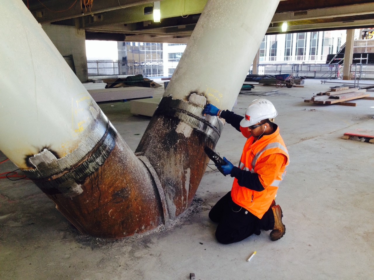
Visual Inspection and Delamination Surveys
Visual and delamination testing are probably the most important of all non-destructive tests. It can often provide valuable information to the well trained eye. Identified features may be related to workmanship, structural serviceability, and material deterioration and it is particularly important that the engineer is able to differentiate between the various signs of distress which may be encountered. These include for instance, delamination, cracks, spalling, pop-outs, disintegration, colour change, weathering, staining, surface blemishes and lack of uniformity.
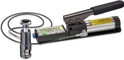
Schmidt Rebound Hammer Testing (Concrete Hardness)
The Schmidt rebound hammer is principally a surface hardness tester. It works on the principle that the rebound of an elastic mass depends on the hardness of the surface against which the mass impinges. There is little apparent theoretical relationship between the strength of concrete and the rebound number of the hammer.
Permeability Testing
Permeability of concrete is important when dealing with durability of concrete particularly in concrete used for water retaining structures or watertight sub-structures. Structures exposed to harsh environmental conditions also require low porosity as well aspermeability. Such adverse elements can result in degradation of reinforced concrete, for example, corrosion of steel leading to an increase in the volume of the steel, cracking and eventual spalling of the concrete. Permeability tests measure the ease with which liquids, ions and gases can penetrate into the concrete.
Resistivity Measurement
There are many techniques used to assess the corrosion risk or activity of steel in concrete. The most commonly used is the half cell potential measurement that determines the risk of corrosion activity. Whilst the half cell potential measurement is effective in locating regions of corrosion activity, it provides no indication of the rate of corrosion. However, a low resistance path between anodic and cathodic sites would normally be associated with a highrate of corrosion than a high resistance path. Such resistivity measurements determine the current levels flowing between anodic and cathodic portions, or the concrete conductivity over the test area, and are usually used in conjunction with the half-cell potential technique. This isan electrolytic process as a consequence of ionic movement in the aqueous pore solution ofthe concrete matrix. An alternative technique to estimate the rate of corrosion, which is becoming increasingly popular, is the linear polarization resistance measurement.
Electromagnetic Methods of Testing Concrete
The physical principle involved can either be by utilizing eddy current effects of magnetic induction effects. With covermeters using eddy current effects, currents in a search coil set up eddy currents in the reinforcement which in turn cause a change in the measured impedance of the search coil. Instruments working on this principle operate at frequencies above 1 kHz and are thus sensitive to the presence of any conducting metal in the vicinity of the search head.
Radiographic Testing
The intensity of a beam of X rays or gamma rays suffers a loss of intensity while passing through a material. This phenomenon is due to the absorption or scattering of the X or gamma rays by the object being exposed. The amount of radiation lost depends on the quality of radiation, the density of the material and the thickness traversed. The beam of radiation, which emerges from the material, is usually used to expose a radiation sensitive film so that different intensities of radiation are revealed as different densities on the film.
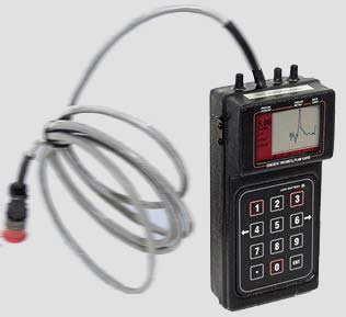
Ultrasonic Testing
A pulse of longitudinal vibrations is produced by an electro-acoustical transducer, whichis held in contact with one surface of the concrete under test. When the pulse generated is transmitted into the concrete from the transducer using a liquid coupling material such as grease or cellulose paste, it undergoes multiple reflections at the boundaries of the different material phases within the concrete. A complex system of stress waves develops, which include both longitudinal and shear waves, and propagates through the concrete. The first waves to reach the receiving transducer are the longitudinal waves, which are converted intoan electrical signal by a second transducer. Electronic timing circuits enable the transit time of the pulse to be measured.
Infrared Thermography
According to the fundamental Law of Planck all objects above absolute zero emitinfrared radiation. This radiation only becomes visible to the human eye when the temperature is above about 500oC. Infrared monitoring equipment has been developed which can detectinfrared emission and visualize it as a visible image. The sensitive range of the detector liesbetween 2 and 14 microns. The 2-5.6 micron range is generally used to visualize temperaturebetween 40oC and 2000oC and the 8-14 micron range is used for temperature between -20oC and ambient temperatures.The thermograms taken with an infrared camera measure the temperature distribution atthe surface of the object at the time of the test. It is important to take into consideration that this temperature distribution is the result of a dynamic process. Taking a thermogram of this object at an earlier or later time may result in a very different temperature distribution. This is especially true when the object has been heated or cooled.
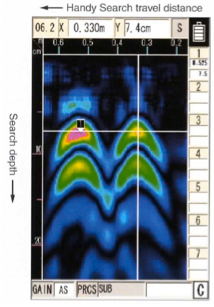
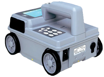
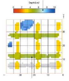
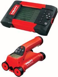
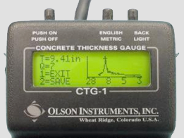
Ground Penetrating Radar (GPR)
Ground penetrating radar (GPR) is a non-destructive technique with a wide range of potential applications in the testing of concrete. It is gaining acceptance as a useful and rapid technique for non-destructive detection of delaminations and the types of defects, which can occur in bare or overlaid reinforced concrete decks. It also shows potential for other applications such as measurement of the thickness of concrete members and void detection.
Radioisotope Gauges
The use of radioisotopes for the non-destructive testing of concrete is based on directing the gamma radiation from a radioisotope against or through the fresh or hardened concrete. When a radiation source and a detector are placed on the same or opposite sides of a concrete sample, a portion of radiation from the source passes through the concrete and reaches the detector where it produces a series of electrical pulses. When these pulses are counted the resulting count or count rate is a measure of the dimensions or physical characteristics, e.g.density of the concrete. Although this radiometry method has not been commonly used on concrete, the increasing use of radioisotopes to measure the compaction of asphalt or bituminous concrete and the soil-aggregate mixtures used in road construction means that the method may be more commonly used in the future. The method has been used, for instance,for density determinations on roller compacted and bridge deck concrete.
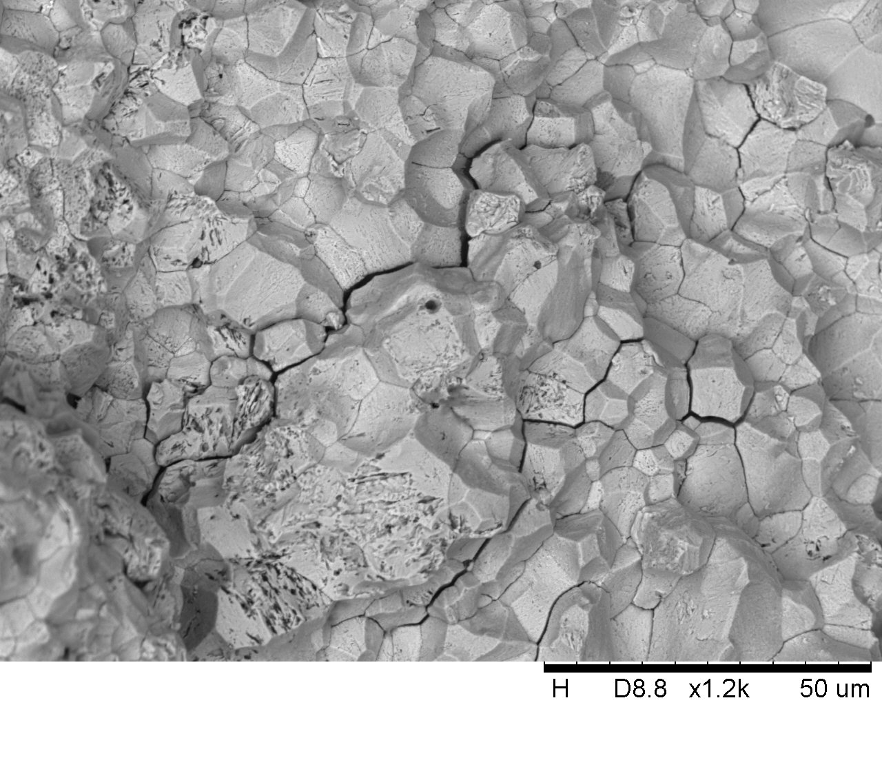
Acousting Emission
Acoustic emissions are microseismic activities originating from within the test specimen when subjected to an external load. Acoustic emissions are caused by local disturbances such as microcracking, dislocation movement, intergranular friction, etc. An acoustic signal travels to a number of piezoelectric transducers, which convert the acoustic signals (mechanical wave forms) to electric signals. A digital oscilloscope captures the electric signals. The time of arrival of the signal at each transducer depends on the distance of the transducer from the AE source. The source, frequency and amplitude of the AE events have been used to quantify the nature of microfracture in various materials. AE sources are determined by calculating the difference in time taken for the wave to arrive at the different transducers. The velocity of the waves in the specimen is determined using the ultrasonic pulse velocity method.
Computed Tomography
Computer tomography (CT), also called computerized radioactive tomography, is there construction of a cross-sectional image of an object from its projections. In other words, it is a coherent superposition of projections obtained using a scanner to reconstruct a pictorial representation of the object.